Auto Carp Fishing Part 2 - Make it Smart and Non-Attended
Dec 04, 2021
Let’s take a look at what’s the common bite alarms with its smartness of “tell you when you’ve got a bite”:
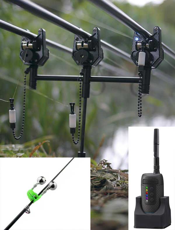
Simplest one is the left bottom one - the bells. The bottom right one is the alarm reciever. The middle one is the bite alarm base.
When a fish gets a bite and tugs at the fishing line, it would apply a force on the fishing line which makes the rod tip bend or vibrates. The simplest bite alarm is a fishing bell-like twin bells, just clamp to the rod tip. The upside is that the fishing bells are cheap, lightweight, no battery is needed; the downside is it is not that sensitive, also the sound is not that loud enough so you could only stay close to where that rod and bells are. Anyway, it does what it needs to do. Here in China, it is widely used. The advanced one is the bite alarm with alarm transmitter(base) and receiver(remote), with an adjustable volume, tone, and sensitivity. The alarm transmitter is like a bell which placed on the rod pod or rod rest kinda bells, however, the alarm receiver is a wireless companion device like a mobile phone which could pick up the signal from the alarm transmitter and alert you by vibrating, lighting up, or emitting a beep themselves with a range of some 50-150 meters(A decent bite alarm receiver like JRC Radar CX Receiver £53.99 = 450RMB, its range could be 150 meters). The range would depend on conditions, for example, how many obstacles are in the way. It gives you some freedom so that you could other things away from the rods like making a coffee and tidying up your barrow.
If you’re not worried about your rods/reels getting stolen and your home is like in 150 meters range to where you’re fishing, then after you could cast out rods and set up the bite alarm, you could just go back home and enjoy yourself.
That’s kinda the idea of what I want to do but it is not smart and stealthy enough. Here are my two cents:
- Smartness.
The bite alarm works like a walkie-talkie (Two-way Radio). The transmitter - the alarm on the rod pod - sends a radio transmission which can be picked up by a receiver best through its antenna. The useful direct range of a two-way radio system depends on lots of radio propagation conditions, basically kinda limited. But I don’t want to have it limited by some distance like 150 meters, I just want it to be as freely used as how we use our smartphones. Also, that style of vibration or beep sound is just boring and archaic, how about some custom Ringtone from the phone in my pocket, e.g, knock on wood, something that every angler would wish they could say to the carps:
Hey, I just met you, and this is crazy. But here’s my number, so call me maybe.
Yeah, Call Me Maybe from Carly Rae Jepsen. vibe :) Just be smart enough to give me a call when it detects the bites.
- Stealthiness.
Leave your eye-catching rods and reels, usually the most expensive fishing tackles, on the bank, is just inviting people to steal. It is best to remove those rods and reels when the cast is done by linking the end of the fishing line to the tent peg staking out on the ground. But this comes with a big challenge when fighting the fish, I will talk later. Also, the Smart Alarm’s components need to be well layout and fit compactly in a case that its size could be as small as possible, so that the whole device could be camouflaged like Rambo to not get distinguished by the passersby, let alone ones from some distance.
Bite Alarm Approaches
There are basically two ways when coming to how we setup the bite alarm, tent stakes with the fishing mainline:
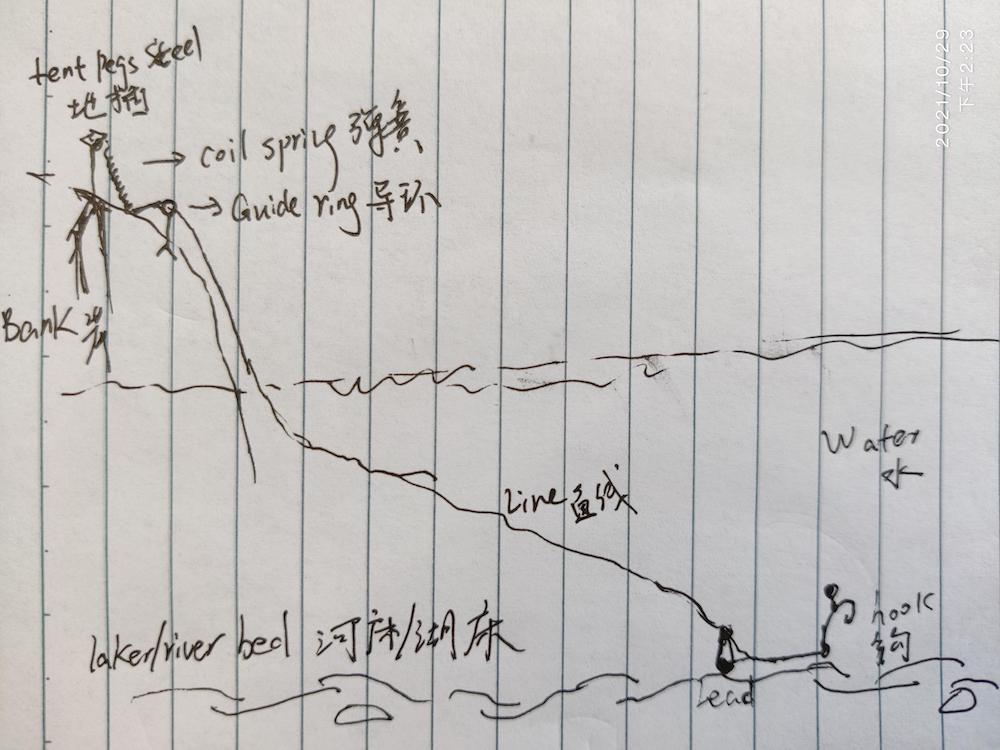 onshore
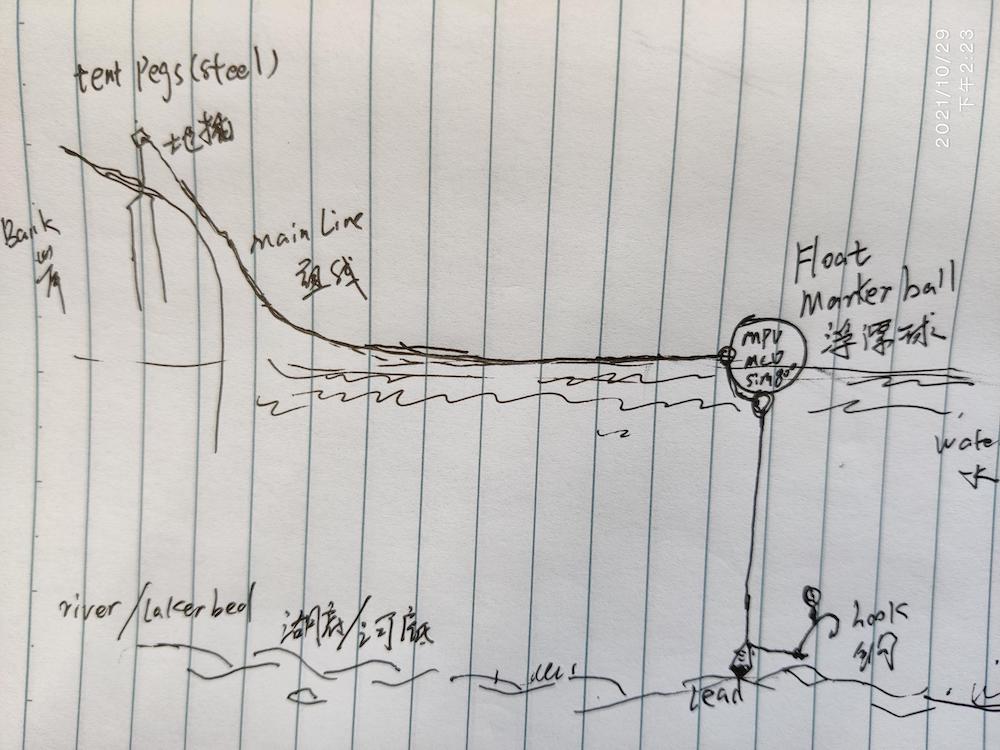 offshore
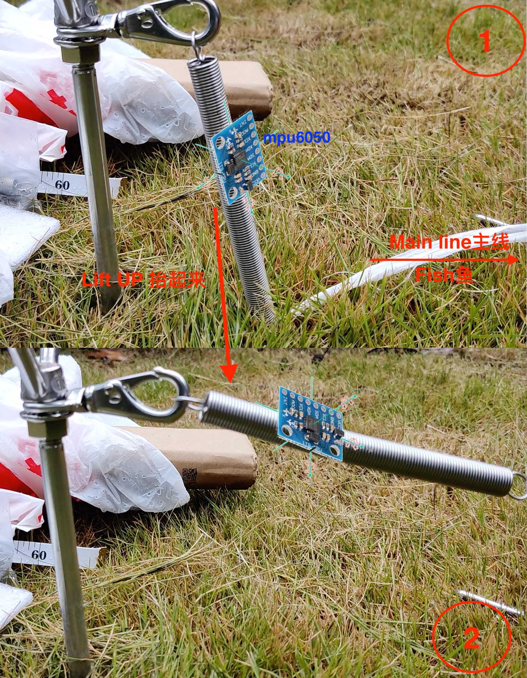
We could put the bite alarm device on the bank or wrap it in a ball-shaped buoyant floater. They share the same idea the sensor part of the device could detect some gyroscope or accelerator changes: either like in the first case you put the senor on the inclined spring and once fish tug the line, the spring will be lifted up and senor could get that angle changes; or in the second case, the senor inside the float ball would detect a vertical acceleration(z-axis) when the fishing line is tugged from the bottom.
To make it more vividly, I did a little experiment to simulate a fish bite like following gif:
Both have pros and cons. The offshore approach’s pros:
- a good stealthiness. People could not reach it easily over the water.
- precision is higher given the shorter distance from float to the fish
- not limited by onshore/bank conditions
- serve as a bite indicator. No matter fishing coming towards the bank or running away from the bank, it always got trigged.
its cons:
- pretty difficult to get it waterproof yet easy to open/close to setup device.
- subject to weather conditions. if too windy or too much current, float ball - the big size and heavyweight - could be pushed back and forth, therefore causing the rigs and lead to moving away. Also if sunlight is strong enough it might get overheat inside the enclosed ball and cause electronics malfunction.
- the casting process gonna be more complicated
- gonna pretty much lose the device, fishing lines, and rigs when it got snagged on the bottom
 I have tried a couple of pe or pvc products with sphere shapes like Gashapon and AB glues but the water resistance still remains a big headache. No existing product that suits my need could be found on taobao.
The onshore approach’s pros:
- no concerns over the waterproofing, heating, etc
- no change in the casting process, just normal casting
- not limited by windy or other harsh weather conditions
- just gonna lose the fishing lines and rigs when the hook got snagged or stuck in the rocks/weeds of the bottom. The bite alarm is intact.
its cons:
- high demand on stealthiness. Still, people could possibly see it and just take it.
- precision of bite signal is not that good given the long-distance fishing line.
- the disguise requires a kinda blending with surroundings.
After weighing trade-offs between onshore and offshore approaches, onshore one seems to be a good start point as it is simpler and materially lower demanded. Next, let’s dive into the detailed mechanism.
Mechanism

- sensor input: data collecting, detect the physical change of angle and acceleration and convert to digital/analog signal.
- mcu coordinator: either poll the input senor or via interrupts to get data and check to see if it meets the criteria. If yes, send commands to an actuator output to perform some physical actions.
- actuator output: establish a connection with a cellular base station nearby, register network. then take commands from MCU, send data over cellular data, and initiate a call to a certain mobile number.
Other than just sending phone-calling command when got a trigger, The MCU controller normally does some heartbeat check every few seconds or minutes by sending very few bits of data to some cloudplatform or backend server to log its health status.
Above is a typical scenario of the buzzword: Internet of Things (IoT). One of the unique things here, which is a good thing, is the communication between mcu and cloud platform is a single direction, i.e, only from MCU to cloudplatform, therefore no need to take any commands from cloudplatform to perform some actions to be autonomous.
A rule of thumb for IoT development is to always have its datasheet something like technical reference/documentation at hand. “More haste, less speed”, it is gonna save you lots of trouble and time. The datasheet is always something you could fall back on when you just have no idea or get into some clueless difficulties.
MCU - ESP8266
Consider the central processor/unit as the brain which is consisted of hardware and software. Based on this central unit there are microcontroller-based IoT boards like Arduino/ESP8266/STM32F and microprocessor-based boards like Raspberry Pi. But how much processing power it needs for our case? Not much. Surely Rasperry PI is overkill. Between the Arduino Uno and NodeMCU ESP8266, the esp8266 is the no-brainer. Arduino Uno board, which was used to be the dominant player in previous years, despite having a very mature and vibrant community, doesn’t have Wi-Fi capability built-in, has a voltage of operation of 5V, a physical size 69 mmx53 mm. Nowadays, NodeMCU ESP8266 board, which comes from a Chinese company Espressif, is the most popular one which comes with Wi-Fi built-in (extremely convenient to get started and play with sth), a voltage of operation of 3.3V(less power and current consumption mean power source could have more options hence cost are lower), a smaller size 58mmx31mm (easier to fit onto the breadboard and have a smaller overall case size to be more stealthy). Look at its price on Taobao:

NodeMCU ESP8266 vs Arudio Uno R3
Apart from that, ESP8266 could be programmed with C/C++ in Arduino IDE just like Arduino Uno. Even though generally bare-metal boards and chips don’t have an operation system, ESP8266 is one heck of IoT microcontroller - it does provide the capability to install some firmwares on the top of the Espressif Non-OS SDK for ESP8266 to abstract and simplify the development process.
Left picture source: #240 Time to Say Goodbye to Arduino and Go On to Micropython/ Adafruit Circuitpython?
from Andreas Spiess.
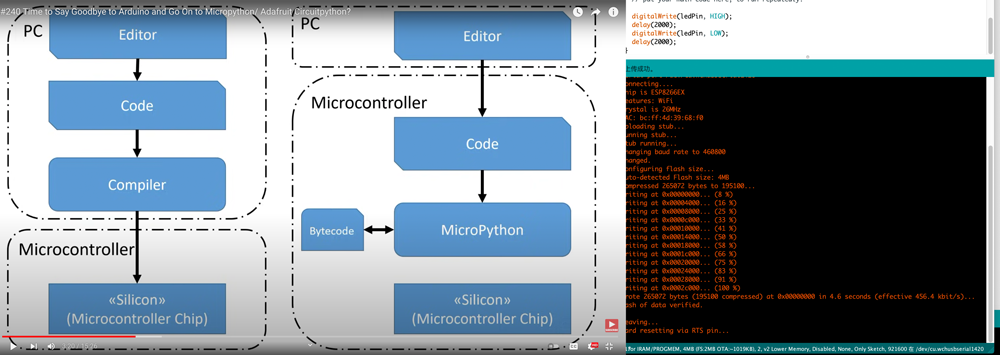
On the right side you could see it took me 4.6 seconds to get led blinking code compile&upload in Arduino IDE
Every time you debug in Arduino IDE is kinda painful, you write in C/C++ code, compile, build and upload to board and this process could take some time even if you tuned some parameters like Tools -> Upload Speed to the max. But with that flashed firmware installed on the board first, you could just write the code in the language you’d like and save it then it got instantly executed on the board. Some language(tailored, not full set of feature) and its firmware for ESP8266 are: Lua based NodeMCU, Python based MicroPython, JavaScript based Mongoose OS. That should be the agile way of iot development :)
After installing the CH340 driver for mac, go to NodeMCU custom builds select modules(I have chosen those modules - bit, file, gpio, i2c, net, node, softuart, tmr, uart) to include for building the firmware. Then open NodeMCU PyFlasher to flash the downloaded bin file of firmware to the board.
Run the jar file of ESPlorer IDE to open the programming gui. The only problem with this on Mac is the serial port of the device sometimes doesn’t show up in the top right dropdown list, even though it is recognized by the system(“ls /dev/tty.*“). I have to go to settings and manually set the serial port of the device.
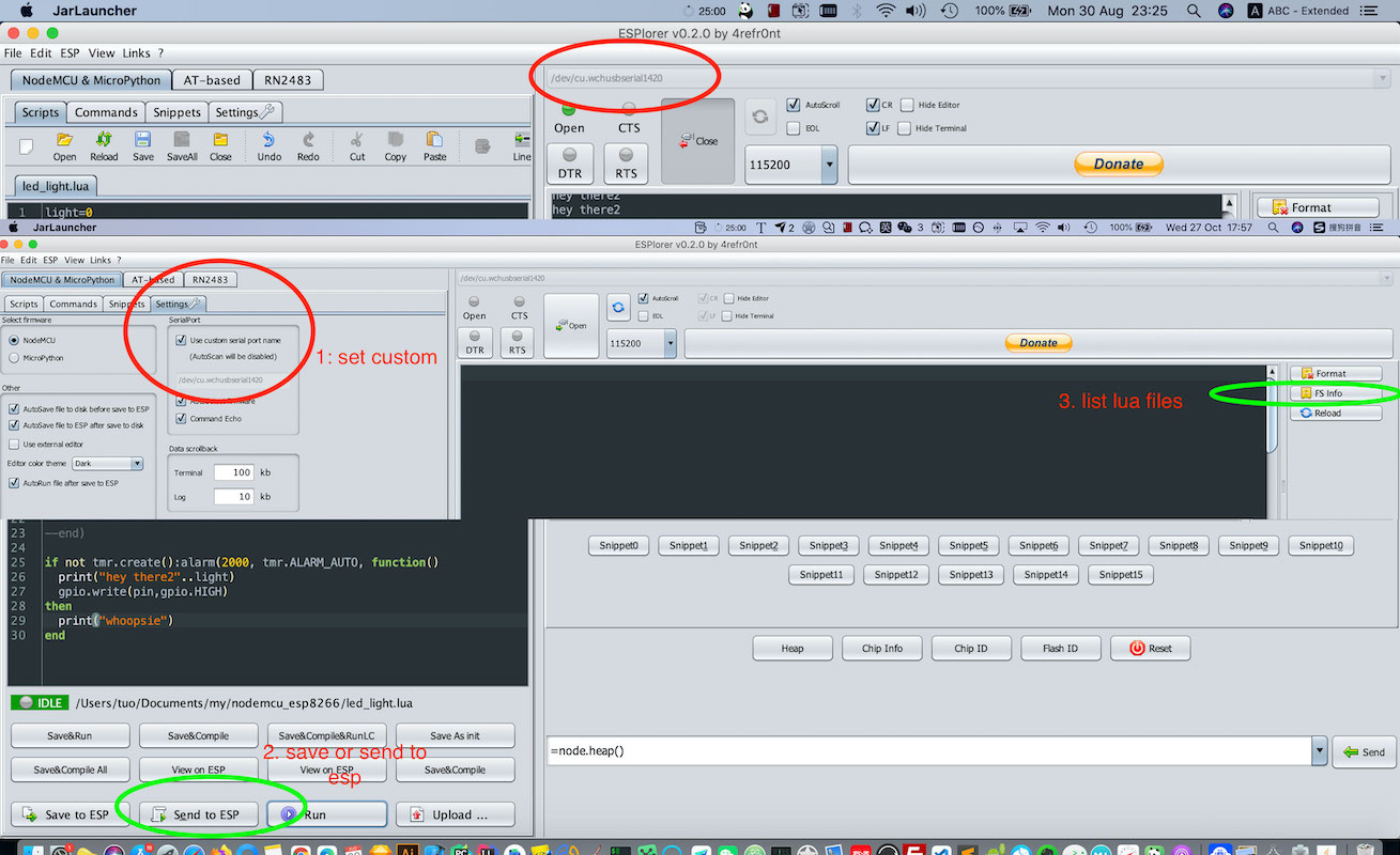
The entrance file of NodeMCU is the init.lua where we’re gonna import files from senor and actuator and code some trigger logic here.
Sensor - MPU-6050
The sensor module for detecting the angle and acceleration is the GY-521 MPU-6050 which is six-axis (Gyro + Accelerometer) + embedded temperature sensor motion tracking device.
We’re just gonna use 4 pins from MPU6050: sda, scl, gnd, vcc. Here is how I wire it with MCU Esp8266 and its schematics:
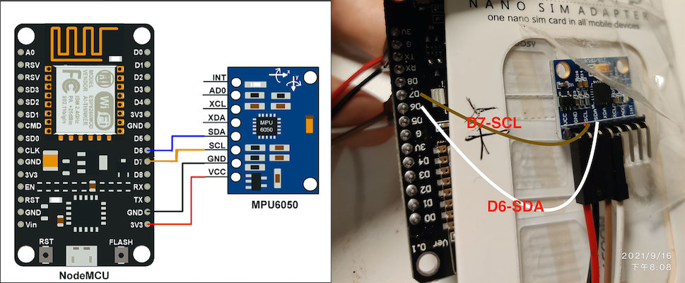
A good tip is to have your wire color coding schemes, for example a brighter color red/orange for vcc positive, a darker color black/blue for ground or earth.
more on: #12 Five Tricks for working with Dupont wires
You might wonder what does the sda and scl mean? Here is a very important topic - serial communication. To be as versatile as possible to communicate with all kinds of peripherals like sensors and actuators, it has a variety of forms of communication - it could be analog (voltage or current) or digital (using a protocol like I2C or SPI or UART). Each protocol has its requirements, limits, and use cases. What MPU-6050 communicates is a I2C(Inter-Integrated-Circuit) 2-Wire protocol. The two wires are serial data (SDA) and serial clock (SCL). The I2C device has some registered addresses for the system bus to look up. That’s something that got mentioned on its datasheet.
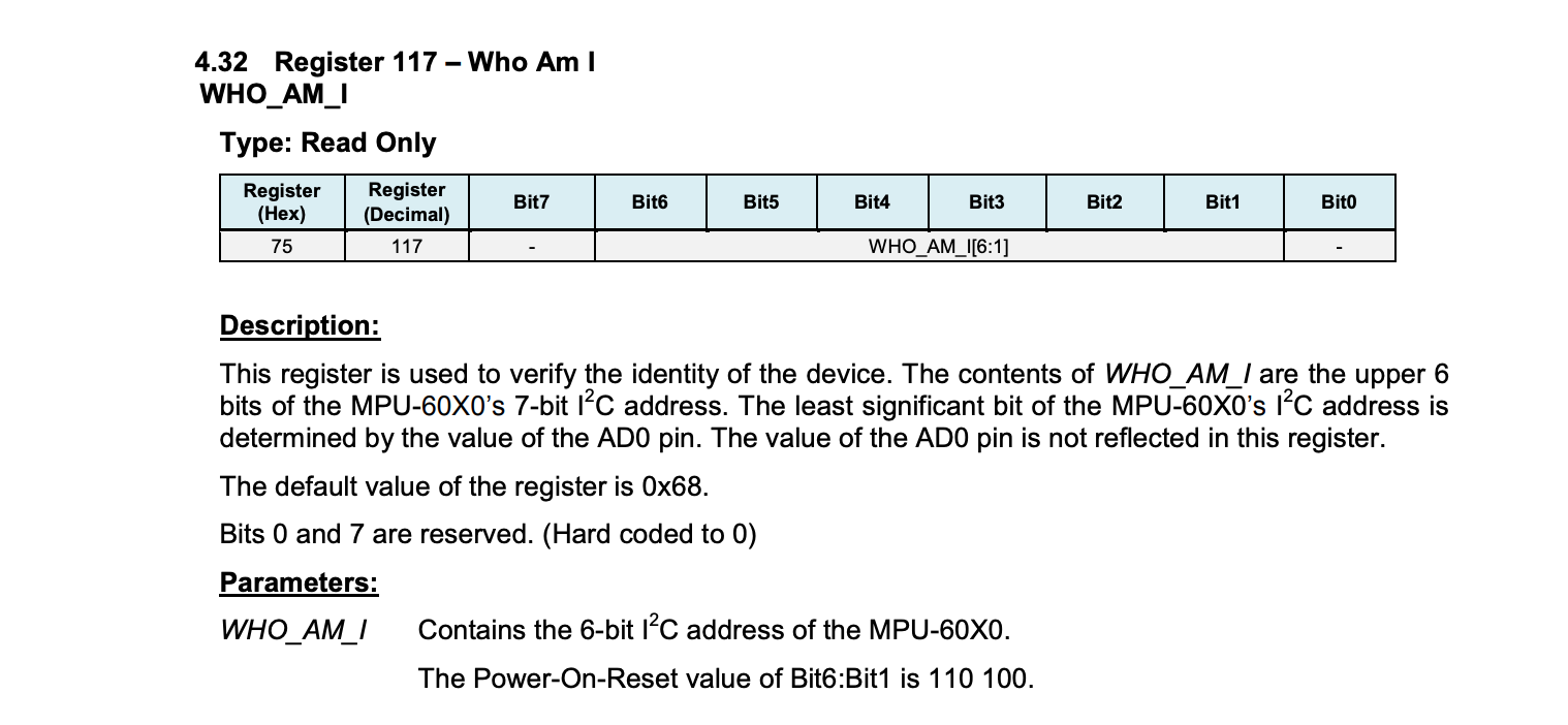 Chapter 4.32 in datasheet of mpu6050
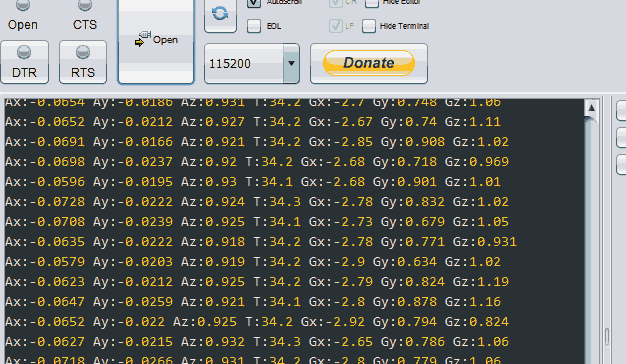
Here is the code snippet for getting gyroscope in degrees/second unit, acceleration in g unit and termperature in degree/celcius. The main flow is setup resolutions like the unit you like to measure in, then inside a loop, retrieves its data and convert with proper scale factor or formula based on the configurations.
The mpu-6050 features a user-programmable gyro full-scale range of ±250, ±500, ±1000, and ±2000 °/sec (dps), and a user-programmable accelerometer full-scale range of ±2g, ±4g, ±8g, and ±16g, which could be found in its datasheet. You could get a more advanced one like Yaw/Pitch/Roll from arduino forum or someone uses it to control a drone. But the above one suffices in my case.
Actuator - SIM800C
In terms of connectivity, we need to take a look at the environment that we will be putting the device. There is no way it could have WIFI on the bank of the lake. Ideally, we want it could make a phone call and send network requests just like our mobile phones. A module that has the GSM for voice calling and sms, and the GPRS for cellular data transfer, would be a good fit.
The frequency of network requests is quite low - the heartbeat rate could be like every 1 minute. No privacy or security concerns here. An HTTP get/post request would work. And the data it needs to send is very small. No video streaming, no need for low latency, so the 3G,4G,5G is kinda overqualified, the best one here is the vintage 2G cellular network.
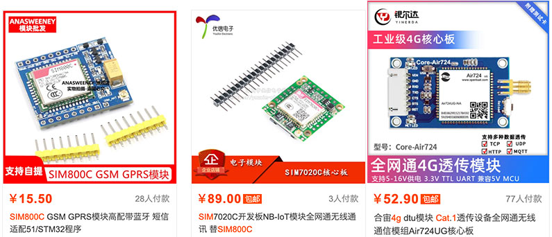
2G is kinda dying out in China. If you’d like you could have NB-IOT as an alternative. SIM7020C is a perfect substitute for SIM800C, with the same dimension and same layout.
SIM800C is a quad-band GSM/GPRS module in a LCC type that supports GPRS up to 85.6kbps data transfer. SIM800C has one SIM card interface. It integrates TCP/IP protocol.SIM800 can be controlled/configured using simple AT commands. MCU can send AT commands over the UART interface and control the SIM800. It can be used for sending/receiving messages, making calls, sending/receiving data over the internet, etc.
You could debug this module with AT commands(Here is the SIM800 Series_AT Command Manual_V1.12) via a USB-TTL converter to connect to your laptop. After connecting, using a wire to shorten the PWX pin on the GND on the sim800c board so that the module could start.
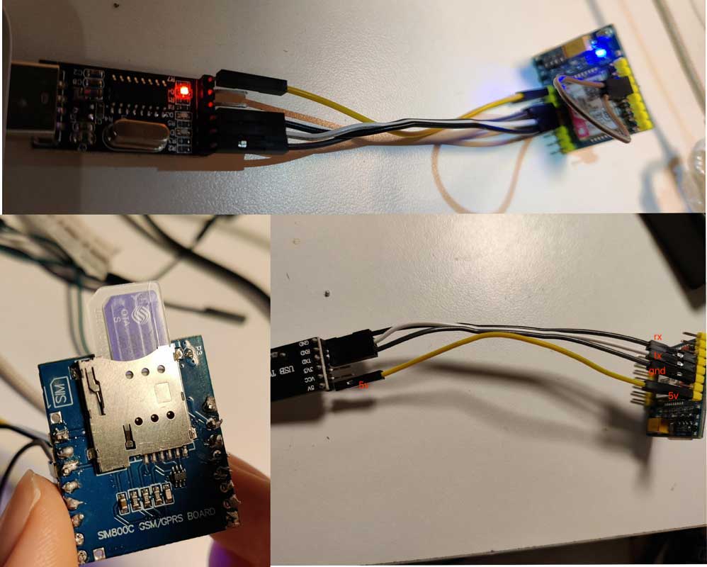
Pay attention the direction and the side of sim card when inserting into the slot
Then we could try AT commands in CoolTermMac on Mac, just choose serial port in Serial Port Options, choose Line Mode in Terminal Mode and switch from View Hex to View ASCII.
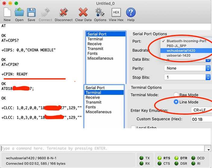
A couple of useful at commands to try out: AT+CPIN? check if sim card is ready; AT+COPS? to check which operator it is registered; AT+CREG? to request network registration status; AT+CSQ to show network signal quality; ATDXxxxxx; to call some phone number
The most important debugging tool for SIM800c is the network LED on the top right side of the SIM800C indicating the status of the cellular network. It has a different blinking rate. When powered up, the led will blink every 1 second to indicate that it is actively searching for a cellular base station therefore not connected to the cellular network yet. When it has made contact with the cellular network & can send/receive voice and SMS, all is good, it will blank every 3 seconds.

SIM800L is pretty much same to SIM800C. source: https://lastminuteengineers.com/sim800l-gsm-module-arduino-tutorial/
Connections and code snippets should be like below:
TX (SIM800C)-RX (D3)
RX (SIM800C)-TX (D2)
GND (SIM800C) - GND (MCU)
VBAT (SIM800C) - VCC (MCU)
Here is my code snippet, you could check out more on my github source repo.
---- Create new software UART with baudrate of 9600, D2 as Tx pin and D3 as Rx pin
function writeCMD(s, cmd)
    print("\n"..tostring(tmr.now())..": send cmd", cmd);
    s:write(cmd.."\n");
end

function sim_setup()
    if not s then
        print("\n"..tostring(tmr.now())..": initilized su\n");
        s = softuart.setup(9600, 2, 3)
        s:on("data", "\n", function(data)
          local txt = string.gsub(data, "[\r\n]", "")
          print("\n"..tostring(tmr.now())..": receive from uart:", txt)
        end)
    else
      print("\n"..tostring(tmr.now())..": existed su\n");
    end
end

function sim_send(txt)
    writeCMD(s, 'AT+SAPBR=3,1,"Contype","GPRS"')
    writeCMD(s, 'AT+SAPBR=3,1,"APN","CMNET"')
    writeCMD(s, 'AT+SAPBR=1,1')
    writeCMD(s, 'AT+SAPBR=2,1')
    writeCMD(s, 'AT+HTTPINIT')
    writeCMD(s, 'AT+HTTPPARA="CID",1')
    local url = "http://xxxx.com/api/heartbeat?time="..tostring(tmr.now().."&txt="..txt)
    writeCMD(s, 'AT+HTTPPARA="URL","'..url..'"')
    writeCMD(s, 'AT+HTTPACTION=0')
    s:write(0x1a);
end

function sim_call()
    writeCMD(s, 'ATD186xxxx5235;')
end
We send an http GET with txt parameter to some url. The txt is the string literal of content from MPU-6050 sensor. From the Nginx log of the backend server, we could see the following log:

As you see, when I put the MPU-6050 on the inclined spring and lift the spring up, from the log, I could see a sudden jump for ax, which I could tell whether something happened or not.
SIM800C Instability
There are lots of people in the forum or on youtube complaining about the stability issue of SIM800. They usually get some weird problems like the module keeps shutting down or the network led light blinks in a chaotic way and it won’t just function in a stable way. And I had this problem too, as you see, from above, how I wire and connect the module with MCU.
Power and current requirements and their consumption is often the most important part of IoT development. The NodeMCU - according to its datasheet, page 7, its operating voltage requirement is from 2.5v to 3.6v and inbuilt LDO voltage regulator of 3.3v - and the sensor, is powered by the one single battery of 18650 3.7v. The power source is another interesting and important topic also for IoT development and lots of factors need put into consideration. 18650 is based Lithium-Ion and is the most commonly used one and it is rechargeable. You could use an expensive one like Lipo based battery. Basically, you need to provide a voltage that is neither too high that is over the module’s upper limit nor too low like the battery keeps discharging and its voltage falls under that desirable voltage of the module making the module keep shutting down. For example, You could use 2 cells of 1.5v Alkaline non-rechargeable battery(1.5v * 2 = 3v), but it is like in the low side of the specification(2.5v-3.6v) and it would waste 50% of the energy of the battery, Or you could use 3 cells of AAA battery (1.5v * 3 = 4.5v), but 4.5v is way over the up limit of the specs (3.6v), therefore you need some LDO regulator to drop the voltage. So for a non-rechargeable battery, you kinda end up with some energy wasting or introducing some complexity. More on the battery supply options for ESP8266, there is a pretty good video from Andreas Spiess on <#64 What is the Ideal Battery Technology to Power 3.3V Devices like the ESP8266?>.
So it is always good to check its specs and datasheet.

Page 17 in chapter 4.1 Power Supply of sim800c datasheet
Most of time, the current consumption is not that much. But during the transmission burst, the current draw could reach to 2A. If the power supply couldn’t source 2A of surge current, its voltage will drop out and if it falls under 3V, the module will be shut down automatically.
The datasheet, suggests two approaches to work around this. (See, the datasheet not only just lists the specs but also provides solutions :))
-
5v LDO (low dropout regulator)
Use 5v power source like power bank etc, then use 2A-rated DC-DC Buck Converter like LM2596(a 3.0A Step-down switching regulator, 2.33RMB ~ 0.3$), connect it to VBAT pin on Sim800C.
-
3.7v Li-ion Battery (Recommended)
Li-ion battery like 18650 3.7v is perfect for the SIM800 module. 2000mAh(could be even smaller), the most commonly seen one, is good enough to provide the correct voltage range even during 2 Amp surge.
I have been using 3.7v Li-ion Battery solution for over two to three months with sim800c and it just works perfectly.
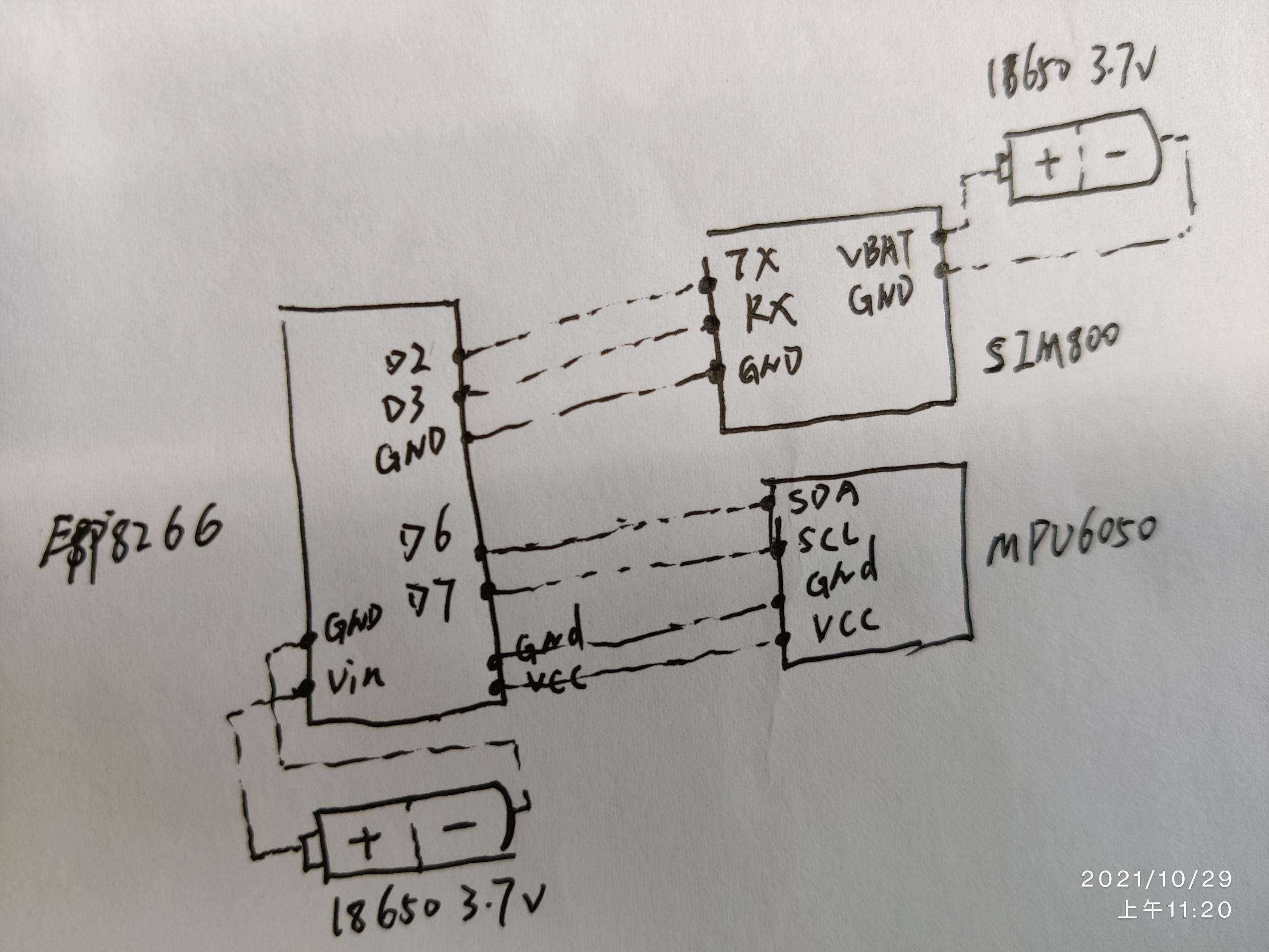
That means we have two 18650 batteries: one for the Esp8266 and MPU-6050, one for the sim800c. Here is the final schematics:
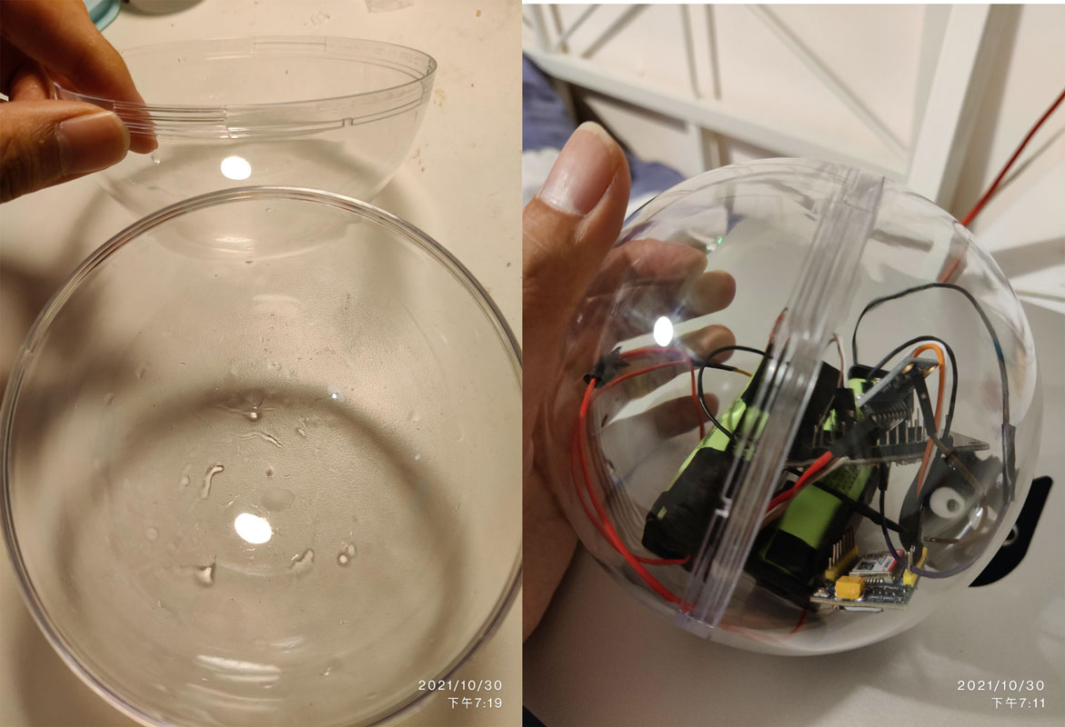
Case Design
Here is the final wires of the device:
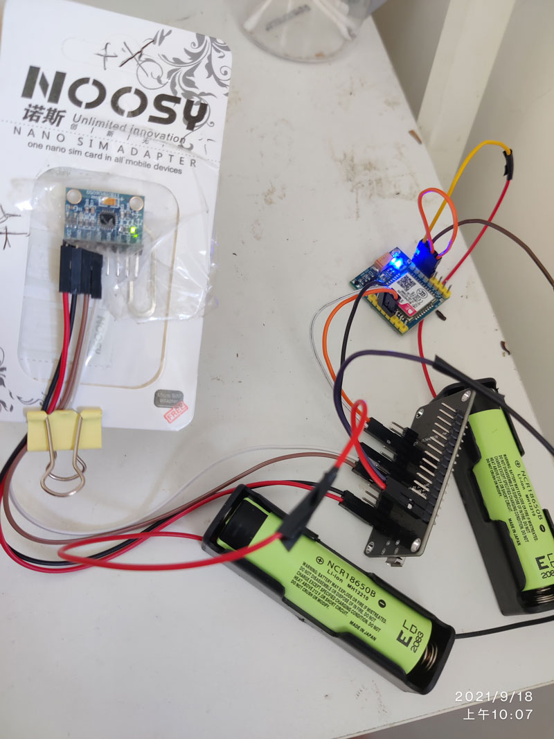
As you could see, the wires are pretty messy. When I try to do a mini test, I found it was so hard to put all the wires/modules inside a case. Also, there is a problem with putting the sensor(mpu-6050) on the spring coil of fishing set and connecting to the MCU inside the device case with non-flexible DuPont lines. The mpu-6050 chip is not easy to bind onto the spring coil and get a steady and same position/angle every time. What’s even worse, 4 wire of Dupont lines imposes a constraint on how we arrange the fishing set and bite alarm device. It is not like regular thread like sewing one which is soft and flexible and easy to twist and extend. Lastly, not only does the device box(the case) need to be waterproof, but also the sensor MPU-6050 needs to be waterproof. In software terms, as what Uncle Bob Martin would say in one of his books Agile Software Development, Principles, Patterns, and Practices, those modules are not loosely coupled and highly cohesive - They expose too much its internal details that caller shouldn’t just be bothered.
If we just revisit why we choose the MPU-6050 as the sensor at the very beginning, given we have chosen the onshore strategy, it looks like it could be replaced with an easier one. The fish tugs the fishing line, how could we use that force to trigger something? If you put “sensor” on the Taobao or Ebay, you could find lots of sensors with different purposes. A YL-99 collision switch senor(2.4RMB - $0.4):
 (The yellow rubber is not needed)
A collision switch could detect force on it and when force is strong enough to push it to be closed, it outputs a low voltage (0), otherwise a high voltage(1).
With this collision switch as the sensor, we could pack the whole modules inside a standalone case then use a sewing thread to connect the device to the fishing line. Now the connecting way is easy and flexible, hence we could put the fishing sets and device anywhere separately I’d like to based on the environment.
Next is how to deal with the messy rampant wires to make it neat and tidy so that it could fit inside a case as small as possible. First, I bought different standard sizes of the breadboard and try how to fit different modules inside it. Second, I measured the approximate dimension(11cm X 15cm X 3cm) that it would take and bought different sizes of PVC plastic cases. And none of the cases would perfectly fit, so I have to cut it with scissors and drill a hole with soldering iron in the side of the box to put the trigger line through.

The new schematics and breadboard wiring sketch:

Here is the finished case:

Demo Test
Then we need some tests to see whether or not it would work and how long the battery life could last. Here is the demo video I record to test:
Imagine the left side is the fishing line, you just tie the device to the fishing line with sewing thread. (The yellow rubber is not needed)
There is a saying in software engineering that when you try to demo to other people, it usually breaks. So I brought it to the office and did a presentation to my colleagues:
I made some adjustments in the init.lua. First, when it starts, it sends a txt saying init to the backend, then sends every 10 seconds for the first 5 minutes, so I could know whether it is properly set up and running ok. Then it sends a heartbeat request with a collision detection result every 30 seconds. The collision poll is every 20 milliseconds, if once the collision is detected, it will call me in an interval of 0, 2, 4 minutes - three times.
-- init.lua
dofile("sim800c_wrapped.lua")
dofile("collison_wrapped.lua")
pin=4 --D4 some visual clue
gpio.mode(pin,gpio.OUTPUT)
gpio.write(pin, gpio.LOW)
tmr.delay(3 * 1000 * 1000) --delay 3 seconds
sim_setup()
gpio.write(pin, gpio.HIGH)
data = collison_read_if_collided()
sim_send("init colided:"..tostring(data))
tmr.delay(1000 * 1000) -- 1 seconds
print("all done, kick off loop");
gpio.write(pin, gpio.LOW)
counter = 0, called = false, shouldCall = false, callCount = 0

sim_timer = tmr.create(), poll_timer = tmr.create()
sim_timer:register(10 *1000, tmr.ALARM_AUTO, function()
    if called == true and shouldCall == false then
        print("should call phone now, after 2.5 min and 5 min");
        if callCount == 0 or callCount == 5 or callCount == 15 then
            sim_call()
        else
            sim_hangoff()
            sim_send(counter..',collided='..tostring(true))
        end
        if callCount == 15 then
            shouldCall = true
        end
        callCount = callCount+1
        gpio.write(pin, gpio.LOW)
    else
        sim_send(counter..',collided='..tostring(data))
        gpio.write(pin, gpio.HIGH)
    end
    gpio.write(pin, gpio.HIGH)
    counter = counter+1
    if counter == 30 then
        sim_timer:interval(30 * 1000);
    end
end)
sim_timer:start()

-- 1000 millseconds
poll_timer:register(1000, tmr.ALARM_AUTO, function()
    data = collison_read_if_collided()
    if data and called == false then
        called = true
        callCount = 0
    end
end)
poll_timer:start()
I also installed the JuiceSSH(a free SSH client for Android) on my phone so that I could check its long anytime anywhere. And the log would also give me a clue if the call is not made somehow.

But with 20 milliseconds poll interval(I assume the force is applied in a very short amount of time) and heartbeat every 30 seconds, the 2500 mAh battery for powering up the MCU gets quickly dyed out, however not for the Sim800C. The polling frequency is just too high. But if we slow down the frequency and do a quick tug, the collision sensor won’t even detect it. How could we do with that?
There is a similar topic in algorithms: Time-Space Trade-Off. To solve it, either in less time and by using more space, or in very little space by spending a long amount of time.
Yes, we gonna use the extension spring, to use its elasticity to create some tension to absorb the strength or force to buy us some time for detecting intervals. Here I add one rubber band on the end of the sensor length line. With this, I could adjust the polling interval to 1 second (1 second is too high, this could be 2 seconds even 5 seconds or 10 seconds in my mini-experiment but this number should be set by the real scenario later but yeah this tweak does show it is possible to detect correctly in a long poll interval).
223.104.210.120 - - [11/Dec/2021:14:52:07 +0800] “GET /api/dashboard?time=3878805&idx=init%20colided:false HTTP/1.1” 301 169 “-“ “SIMCOM_MODULE”
223.104.210.120 - - [12/Dec/2021:16:36:14 +0800] “GET /api/dashboard?time=305340902&idx=542,collided=false HTTP/1.1” 301 169 “-“ “SIMCOM_MODULE”
Polling every 1 seconds from switch; sending every 3 minutes heartbeat - 2500mAh - it could last like 25-26 hours; for 3200 mAh it could last 36-38 hours. Not too bad!
Real Test
With the all work done, it is a good time to put it to the real test. I happened to have two-three days off and so I went back home. And in that reservoir, the water has dropped down so much, so the rice field side is just full of mud and I just picked the mountainside for fishing.
I cast out, connected the fishing mainline to the staked tent pegs, then link the mainline with the device using a thread, and carefully disguised the device and tent pegs with rocks on the top of it. I looked at the ssh console, all good, so I just went back home around 3PM afternoon.

I’m pretty happy with the stealthiness. You basically couldn’t recognize it even if you pass it by.
The morning of the second day, around 7:50Am, I got three calls on my phone.I was pretty excited and rushed to the bank imaging how big the fish could be. By the time I got to the bank, I was just jaw-dropping to see three or four ducks sitting right on the spot where I set up my device and trigger. I was like “oh shit, no way” :)

I went to check my lines and bite alarm device. It turned out the fishing line and the trigger thread got twisted in total chaos.

No wonder it got trigged! I did not notice those ducks that afternoon when I set up. Then I changed with another pair of batteries and moved the whole set to another venue that ducks couldn’t reach easily.
That later two days it turned to be blank. I wasn’t disappointed since I knew this was a brand new venue, had only one set of rod&reel&line&rig, and esp in winter, it was pretty tricky to get a bite. Instead, the process of trial-and-error has so much fun and I definitely will keep trying it out if later I have another holiday. Keep tuned!
Improvements
There are some possible improvements we could do. Add extra 20 meters lines between the tent pegs and mainline to give it extra buffer when the fish is tugging the line. Also could add some rubber band to the tent peg to counter the force of the fish to simulate what the rod does. The lead and sinker need to be slidable within some range if not droppable, to alleviate the panic of the fish after getting a bite.
The polling style could be changed to using interrupts. Together with the sleep mode of Esp8266, you could make the battery lasts a very long time. But the downside is you won’t get the heartbeat http request.
Possible replace 2G with NB-IoT. No need a real sim card, you could just use e-simcard. So you won’t be too worried when your device is stolen by someone else, therefore, they got your sim card and inserted it into their phone and do some bad things. The downside is it can’t make a voice call (could be resolved by calling Twilio api to make calls from them) and the module SIM7020C is a little bit more expensive.
Prices
Only the battery part is kinda expensive (over 20RMB). Actually 2000 mAh for SIM800C and 2600 mAh for MCU is good enough.

Source Code and Datasheets
- Source Code on Github (C&Lua): tuo/auto_carp_fishing
- ESP8266 Technical Reference
- SIM800C Datasheet
- MPU6050 Datasheet
References
Some good blogs and forums:
Some good youtube channels:
Some good articles:
- A Complete Guide on How to Create an IoT Product
- A Comprehensive Guide to Start Building an IoT Product
- A short yet good coverage on the cases of NB-IoT NB-IoT Commercial Premier Use Case Library by HuaWei
- NODEMCU ESP8266 VS ARDUINO UNO
- #12 Five Tricks for working with Dupont wires
- Microcontroller Connection Protocols: W1, I2C, SPI, UART
- How ELECTRICITY works - working principle
- 《MPU-6050 6dof IMU tutorial for auto-leveling quadcopters with Arduino - Part 1》
- 《MPU-6050 6dof IMU tutorial for auto-leveling quadcopters with Arduino - Part 2》
- SIM800C GSM/GPRS HAT
- <#64 What is the Ideal Battery Technology to Power 3.3V Devices like the ESP8266?>